


Displacement Current
It is a current which produces in the region in which the electric field and hence the electric flux changes with time.
Displacement current, ID = εo . dφE / dt
where, φE is the electric flux.
Ampere-Maxwell Law

where, μo = Permeability
= 4π * 10-7 V / Am
Maxwell’s Equations
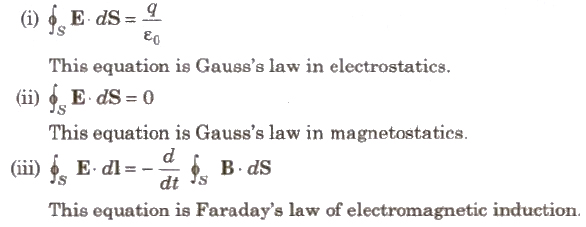

This equation is Ampere-Maxwell law.
Electromagnetic Waves
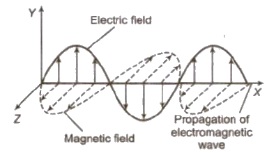
Electromagnetic waves are those waves in which electric and magnetic field vectors changes sinusoidally and are perpendicular to each other as well as at right angles to the direction of propagation of wave.
The equation of plane progressive electromagnetic wave can be written as E = Eo sin Ω (t – x / c) and B = Bo sin Ω (t – x / c). Where, Ω =2πv
Electromagnetic waves are produced by accelerated charge particles.
Properties of EM Waves
(i) These waves are transverse in nature.
(ii) These waves propagate through space with speed of light, i.e., 3 * 108 m / s.
(iii) The speed of electromagnetic wave,
c = 1 / √μo εo
where, μoo is permittivity of free space,
∴ c = Eo / Bo
where Eo and Bo are maximum values of electric and magnetic field vectors.
[According to Maxwell, when a charged particle is accelerated, it produces electromagnetic wave. The total radiant flux at any instant is given by,
p = q2a2 / 6 πεoc2
(iv) The rate of flow of energy in an electromagnetic wave is described by the vector S called the poynting vector, which is ; defined by the expression,
S = 1 / μo E * B
SI unit of Sis watt/m2.
(v) Its magnitude S is related to the rate at which energy is transported by a wave across a unit area at any instant.
(vi) The energy in electromagnetic waves is divided equally between electric field and magnetic field vectors.
(vii) The average electric energy density.
UE = 1 / 2 εo E2 = 1 / 4 εo E2o
(viii) The average magnetic energy density,
UB = 1 / 2 B2 / μo = 1 / B2o / μo
(ix) The electric vector is responsible for the optical effects of an electromagnetic wave.
(x) Intensity of electromagnetic wave is defined as energy crossing per unit area per unit time perpendicular to the directions of propagation of electromagnetic wave.
(xi) The intensity I is given by the relation,
I = < μ > c = 1 / 2 εo E2oc
(xii) The existence of electromagnetic waves was confirmed by Hertz experimentally in 1888.
Propagation of Electromagnetic Waves
In radio wave communication between two places. the electromagnetic waves are radiated out by the transmitter antenna at one place which travel through the space and reach the receiving antenna at the other place.
Electromagnetic Spectrum
The arranged array of electromagnetic radiations in the sequence of their wavelength or frequency is called electromagnetic spectrum
Radio and microwaves are used in radio and TV communication,
Infrared rays are used to
(i) Treat muscular straw.
(ii) For taking photographs’ in fog or smoke.
(iii) In green house to keep plants warm.
(iv) In weather forecasting through infrared photography.
Ultraviolet rays are used
(i) In the study of molecular structure.
(ii) In sterilizing the surgical instruments.
(iii) In the detection of forged documents, £ringer prints.
X-rays are used
(i) In detecting faults, cracks, flaws and holes in metal products.
(ii) In the study of crystal structure.
(iii) For the detection of pearls in oysters.
γ – rays are used for the study of nuclear structure.
Earth’s Atmosphere
The gaseous envelope surrounding the earth is called earth’s atmosphere. It contain the following layers
(i) Troposphere This region extends upto a height of 12 km from earth’s surface.
(ii) Stratosphere This region extends from 12 km to 50 km. In this region, most of the atmospheric ozone is concentrated from 30 to 50 km. This layer is called ozone layer.
(iii) Mesosphere The region extends from 50 km to 80 km.
(iv) Ionosphere This region extends from 80 km to 400 km.
In ionosphere the electron density is very large in a region beyond 110 km from earth’s surface which extends vertically for a few kilometer.
This layer is called Kennelly Heaviside layer.
In ionosphere a layer having large electron density is found at height 250 km from earth’s surface, called Appleton layer.
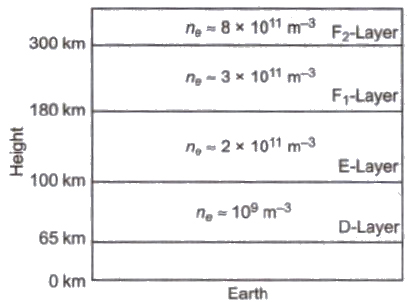
There are four main layers in earth’s atmosphere having high density of electrons and positive ions, produced due to ionisation by the high energy particles coming from sun. star or cosmos. These layers play their effective role in space communication. These layers are D, E, F1 and F2.
(i) D-layer is at a virtual height of 65 km from surface of earth and having electron density = 109 m-3
(ii) E-layer is at a virtual height of 100 km, from the surface of earth, having electron density = 2 * 1011 m-3
(iii) F1-layer is at a virtual height of 180 km from the surface of earth, having electron density = 3 * 1011 m-3
(iv) F2 – layer is at a vertical height of about 300 km in night time and about 250 to 400 km in day time. The electron density of this layer is = 8 * 1011 m-3
Communication
Faithful transmission of information from one place to another place is called communication.
Optical fibers are used in optical communication.

Communication System
A communication system contains three main parts
(i) Transmitter It process and encode the information and make it suitable for transmission.
The message signal for communication can be analog signals or digital signals.
An analog signal can be converted suitably into a digital signal and vice-versa.
[An analog signal is that in which current or voltage value varies continuously with time.
A digital signal is a discontinuous function of time. Such a signal is usually in the form of pulses.]
(ii) Communication Channel The medium through which information propagate from transmitter to receiver 1S called communication channel.
(iii) Receiver It receives and decode the signal.
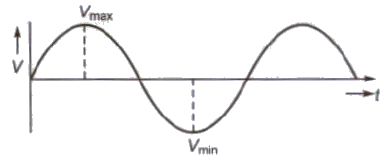
Analog Signal
A signal in which current or voltage changes its magnitude continuously with time, is called an analog signal.
Digital Signal
A signal in which current or voltage have only two values, is called a digital signal.
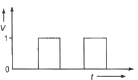
Note An analog signal can be converted suitable Into a digital signal and vice-versa.
Modulation
The process of superimposing the audio signal over a high frequency carrier wave is called modulation.
In the process of modulation anyone characteristic of carrier wave is varied in accordance with the instantaneous value of audio signal (modulating signal).
Need of Modulation
(i) Energy carried by low frequency audio waves (20 Hz to 20000 Hz) is very small.
(ii) For efficient radiation and reception of signal. the transmitting and receiving antennas should be very high approximately 5000 m.
(iii) The frequency range of audio signal is so small that overlapping of signals create a confusion.
Types of Modulation
(i) Amplitude Modulation In this type of modulation, the amplitude of high frequency carrier wave is varied in accordance to instantaneous amplitude of modulating signal.
Band width required for amplitude modulation
= twice the frequency of the modulating signal.
(ii) Frequency Modulation In this type of modulation, the frequency of high frequency carrier wave is varied in accordance to instantaneous frequency of modulating signal.
(iii) Pulse Modulation In this type of modulation, the continuous waveforms are sampled at regular intervals. Information is transmitted only at the sampling times.
Demodulation
The process of separating of audio signal from modulated signal is called demodulation.
Antenna
An antenna converts electrical energy into electromagnetic waves at transmitting end and pick up transmitted signal at receiving end and converts electromagnetic waves into electrical signal.
Modem
The term modem is contraction of the term modulator and demodulator. Modem is a device which can modulate as well as demodulate the signal. It connect one computer to another through ordinary telephone lines.
Fax (Facsimile Telegraphy)
The electronic reproduction of a document at a distant place is called FAX
Radio Waves
The radio waves are the electromagnetic waves of frequency ranging from 500 kHz to about 1000 MHz. These \V8VeS are used In the field of radio communication. With reference to the frequency range and wavelength range, the radio waves have been divided into various categories shown in table.
Frequency Range and Wavelength Range of Radio Waves

Propagation of Radio Waves
The three modes are discussed below.
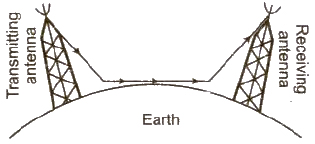
(i) Ground Wave or Surface Wave Propagation It is suitable for low and medium frequency up to 2 MHz. It is used for local broad casting.
(ii) Sky Wave Propagation It is suitable for radio waves of frequency between 2 MHz to 30 MHz. It is used for long distance radio communication.
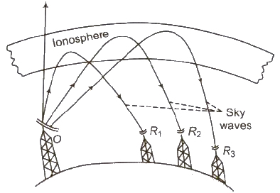
Critical Frequency The highest frequency of radio wave that can be reflected back by the ionosphere is called critical frequency.
Critical frequency, vc = 9 (Nmax)1 / 2
Where, Nmax = number density of electrons/metre3.
Skip Distance The minimum distance from the transmitter at which a sky wave of a frequency but not more than critical frequency, is sent back to the earth.
Skip distance (Dskip) = 2h (Vmax / Vc)2 – 1
where h is height of reflecting layer of atmosphere,
Vmax is maximum frequency of electromagnetic waves and Vc is critical frequency.
Fading The variation in the strength of a signal at receiver due to interference of waves, is called fading.
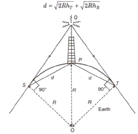
(iii) Space Wave Propagation It is suitable for 30 MHz to 300 MHz. It is used in television communication and radar communication. It is also called line of sight communication.
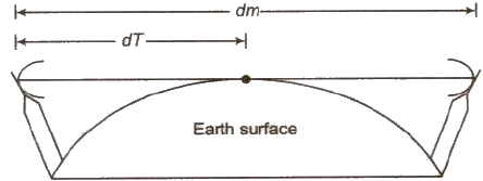
d = √2RH
Microwave Propagation
Satellite Communication
It IS carried out between a transmitter and a receiver through a satellite. A geostationary satellite is utilized for this purpose, whose time period is 24 hours.
A communication satellite is a space craft, provided with microwave receiver and transmitter. It is placed in an orbit around the earth. The India remote sensing satellites are
IRS-IA, IRS-IB and IRS-IC
The line-of-sight microwave communication through satellite is possible if the communication satellite is always at a fixed location with respect to the earth, e.g., the satellite which is acting as a repeater must be at rest with respect to the earth. It is so far a satellite known as geo-stationary satellite.
The basic requirements for geostationary satellites are as follows:
The orbit in which the gee-satellite above revolves around the earth is known as geo-synchronous orbit. As its angular speed is synchronised with the angular speed of the earth. therefore, the geo-stationary satellite is also known as geo-synchronous satellite.
Merits of Satellites Communication
Demerits of Satellite Communication
1. If a system on the satellite goes out of order due to environmental stresses, it is almost impossible to repair it.
2. In satellite communication, there is a time delay between transmission and reception, due to extremely large communication path length (greater than 2 x 36000 km). This delay causes a time gap during talking, which proves quite annoying.
Remote Sensing
It is a technique of observing or measuring the characteristics of the object at a distance. A polar satellite is utilized for this purpose.
Distance upto which a signal can be obtained from an antenna is given by
d = √2hR
where, h is height of antenna and R is radius of earth.
LED and Diode Laser in Communication
Light Emitting. Diode (LED) and diode laser are preferred sources for optical communication links to the following features.
Line Communication
Optical Fibres
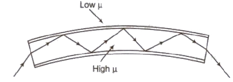
An optical fibre is a long thread consisting of a central core of glass or plastic of uniform refractive index. It is surrounded by a cladding of material of refractive index less than that of the core and a protective Jacket of insulating material.
There are three types of optical fibre configuration
Applications of Optical Fibres
.png)