


Transient Current
An electric current which vary for a small finite time, while growing from zero to maximum or decaying from maximum to zero, is called a transient current.
Growth of Current in an Inductor
Growth of current in an inductor at any instant of time t is given by
I = Io(1 – e -Rt / L)
where, Io = maximum current, L = self inductance of the inductor and R = resistance of the circuit.
Here R / L = τ, is called time constant of a L – R circuit.
Time constant of a L – R circuit is the time in which current in the circuit grows to 63.2% of the maximum value of current.
Decay of current in an inductor at any time t is given by
I = Ioe -Rt / L
Time constant of a L – R circuit is the time in which current decays to 36.8% of the maximum value of current.
Charging and Discharging of a Capacitor
The instantaneous charge on a capacitor on charging at any instant of time t is given by
q = qo(1 – e – t / RC)
where RC = τ, is called time constant of a R – C circuit.
The instantaneous charge on a capacitor in discharging at any instant of time t is given by q = qoe – t / RC
Time constant of a R – C circuit is the time in which charge in the capacitor grows to 63.8% or decay to 36.8% of the maximum charge on capacitor.
Alternating Current
An electric current whose magnitude changes continuously with time and changes its direction periodically, is called an alternating current.
The instantaneous value of alternating current at any instant of time t is given by
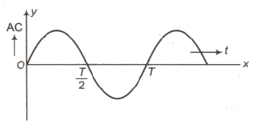
I = Io sin ωt
where, 10 = peak value of alternating current.
The variation of alternating current with time is shown in graph given below
Mean or average value of alternating current for first half cycle
Im = 2Io / π = 0.637 Io
Mean or average value of alternating current for next half cycle
I’m = – 2Io / π = – 0.637 Io
Mean or average value of alternating current for one complete cycle = O.
Root mean square value of alternating current
Iv = Irms = Io / √2 = 0.707 Io
Where, Io = peak value of alternating current.
Root mean square value of alternating voltage
Vrms = Vo / √2 = 0.707 Io = 0.707 Vo
Reactance
The opposition offered by an inductor or by a capacitor in the path of flow of alternating current is called reactance.
Reactance is of two types
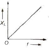
(i) Inductive Reactance (XL) Inductive reactance is the resistance offered by an inductor.
Inductive reactance (XL) = Lω = L2πf = L2π / T
Its unit is ohm. XL ∝ f
For direct current, XL = 0 (f = 0)
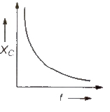
(ii) Capacitive Reactance (Xc) Capacitive reactance is the resistance offered by an inductor
Capacitive reactance,
Xc = 1 / Cω = 1 / C2πf = T / C 2π
Its unit is ohm Xc ∝ 1 / f
For direct current, Xc = ∞ (f = 0)
Impedance
The opposition offered by an AC circuit containing more than one out of three components L, C and R, is called impedance (Z) of the circuit.
Impedance of an AC circuit, Z = √R2 + (XL – XC)2
Its SI unit is ohm.
Power in an AC Circuit
The power is defined as the rate at which work is being in the circuit.
The average power in an AC circuit,
Pav = Vrms irms cos θ
= V / √2 i / √2 cos θ = Vi / √2 cos θ
where, cos θ = Resistance(R) / Impedance (Z) is called the power factor 0f AC circuit.
Current and Potential Relations
Here, we will discuss current and potential relations for different AC circuits.
(i) Pure Resistive Circuit (R circuit)
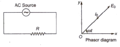
(a) Alternating emf, E = Eo sin ωt
(b) Alternating current, I = Io sin ωt
(c) Alternating emf and alternating current both are in the same phase.
(d) Average power decay, (P) = Ev . Iv
(e) Power factor, cos θ = 1
(ii) Pure Inductive Circuit (L Circuit)
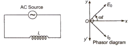
(a) Alternating emf, E = Eo sin ωt
(b) Alternating current, I = Io sin (ωt – π / 2)
(c) Alternating current lags behind alternating emf by π / 2.
(d) Inductive reactance, XL = Lω = L2πf
(e) Average power decay, (P) = 0
(f) Power factor, cos θ = cos 90° = 0
(iii) Pure Capacitive Circuit
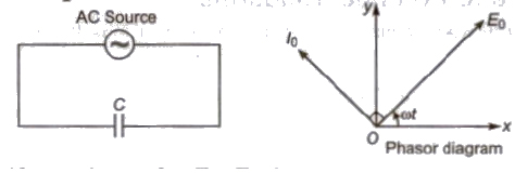
(a) Alternating emf, E = Eo sin ωt
(b) Alternating current, I = Io sin (ωt + π / 2)
(c) Alternating current lags behind alternating emf by π / 2.
(d) Inductive reactance, XL = Cω = C2πf
(e) Average power decay, (P) = 0
(f) Power factor, cos θ = cos 90° = 0
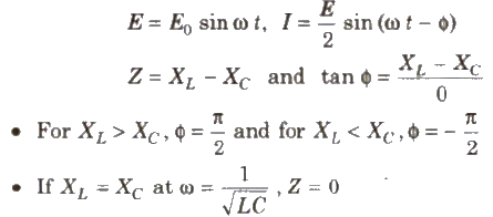
(iv) R – C Circuit
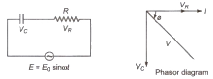
E = Eo sin ωt
I = Eo / 2 sin (ωt – φ)
Z = √R2 + (1 / ωC)2
tan φ = – 1 / ωC / R
Current leading the voltage by φ
V2 = V2R = V2C
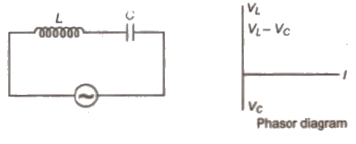
(v) L – C Circuit
(vi) L – C – R Circuit
(a) Alternating emf, E = Eo sin Ωt
(b) Alternating current, I = Io sin (Ωt ± θ)
(c) Alternating current lags leads behind alternating emf by ω.
(d) Resultant voltage, V = √V2R + (VL – VC)2
(e) Impedance, Z = √R2 + (XL – XC)2
(f) Power factor, cos θ = R / Z = R / √√R2 + (XL – XC)2
(g) Average power decay, (P)= EVIV cos θ
Resonance in AC Circuit
The condition in which current is maximum or impedance is minimum in an AC circuit, is called resonance.
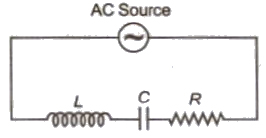
(i) Series Resonance Circuit
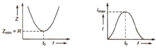
In this circuit components L, C and R are connected in series.
At resonance = XL = XC
Resonance frequency f = 1 / 2π√LC
A series resonance circuit is also known as acception circuit.
(ii) Parallel Resonance Circuit
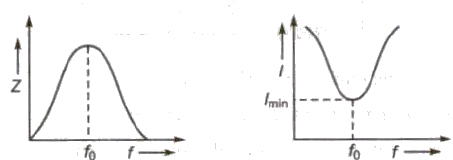
In this circuit L and C are connected in parallel with each other.
At resonance, XL = XC
Impedance (Z) of the circuit is maximum.
Current in the circuit is minimum.
Wattless Current
Average power is given by
Pav = Erms = Irms cos θ
Here the Irms cos φ contributes for power dissipation. Therefore, it is called wattless current.
AC Generator or Dynamo
It is a device which converts mechanical energy into alternating current energy.
Its working is based on electromagnetic induction.
The induced emf produced by the AC generator is given by
e = NBAω sin ωt = eo = sin ωt
There are four main parts of an AC generator
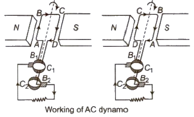
(i) Armature It is rectangular coil of insulated copper wire having a large number of turns.
(ii) Field Magnets These are two pole pieces of a strong electromagnet.
(iii) Slip Rings These are two hollow metallic rings.
(iv) Brushes These are two flexible metals or carbon rods, which remains slightly in contact with slip rings .
Note An DC generator or dynamo contains split rings or commutator inspite of slip rings.
DC Motor
It is a device which converts electrical energy into mechanical energy.
Its working is based on the fact that when a current carrying coil is placed in uniform magnetic field a torque acts on it.
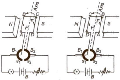
Torque acting on a current carrying coil placed in uniform magnetic field
τ = NBIA sin θ
When armature coil rotates a back emf is produced in the coil.
Efficiency of a motor,
η = Back emf / Applied emf = E / V
Transformer
It is a device which can change a low voltage of high current into a high voltage of low current and vice-versa.
Its working is based on mutual induction.
There are two types of transformers.
(i) Step-up Transformers It converts a low voltage of high current into a high voltage of low current.
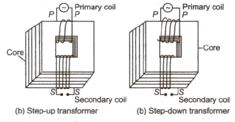
In this transformer,
Ns > NP, Es > EP
and IP > IS
(ii) Step-down Transformer It converts a high voltage of low current into a low voltage of high current.
In this transformer,
NP > NS, EP > ES and IP < IS
Transformation Ratio
Transformation ratio,
K = NS / NP = ES / EP = IP / IS
For step-up transformer, K > 1
For step-down transformer, K < 1
Energy Losses in a Transformer
The main energy losses in a transformer are given below
Important Points
Generally efficiency ranges from 70% to 90%.
It is based on the phenomenon of mutual induction.

.png)


